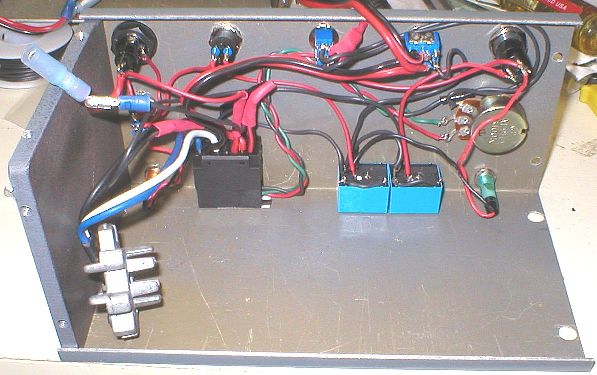
X-Axis Powerfeed for Mini Mills Part 3 The last step was to complete the case and mount the controls. The ends of the case are 1/4" steel plate. I made the rest of the case out of an old aluminum panel I had lying around. The picture below shows everything mounted on the front panel except the heatsink for the MOSFET. The black object toward the lower left corner is the switch housing from the drill. The two blue objects to the right of it are the relays that I used to switch the motor
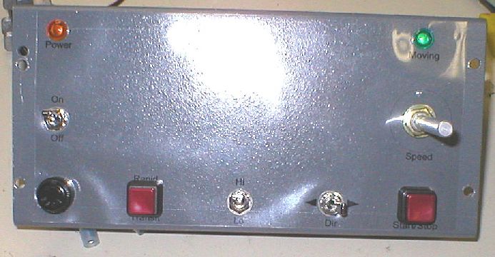
Here's an outside view of the front panel:
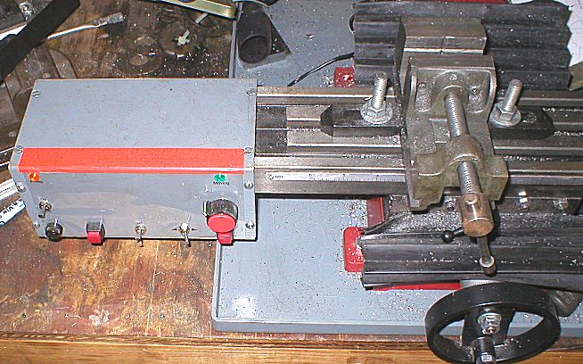
First an explanation for the lousy label job. I like to draw labels with a CAD program and then reverse them and print them on a transparent sheet usually used for overhead projectors. I then normally spray them with spray-on contact cement but I was out of it this time and was in too big of a hurry to get this thing going so I put it on and let the installed controls hold it in place. You can tell from the above picture that this didn't work so well and I also need to move a few of the labels around so someday I'll redo it. For now though I'll leave well enough alone. It did have a tendancy to allow chips to fall behind it so I added a strip of tape to the top to seal it. I added an amber light to show when power is switched on and a green light to show when the motor is being driven. The round black item in the lower left corner is a fuse holder. So far I'm very happy with the end result. It works really well and saves me a lot of cranking. After a bit of adjustment the clutch slips if I forget to unlock the X-axis, and at end of travel but I don't believe it's ever slipped for normal cutting. Here's the finished product:
The only problem I've had is that I should have adjusted the lead screw before I made the mounting plate because it's not exactly centered at the powerfeed end and this causes it to tighten up near the end of travel in one direction. The only other thing I would do different if I built another one is to mount all of the controls toward the left end of the case because the speed knob and start/stop switch are a bit hard to get to when the table moves all the way to the right. As for a parts list, I don't really have one but here's a basic rundown of the electronic parts without specific part numbers. There are many different styles available so you can pick whatever you like.:
Total cost for the whole project was around $30-$35 but I already had all of the mechanical parts except for the drill itself, and a few of the electronic parts. I paid a premium price for a couple of the switches and the relays because I wanted them in a hurry and Radio Shack is a bit pricey and the only game in town. IIRC a SPST switch like the one I used for the power switch is about $3 but if you order from someone like Mouser, MECI or MPJA they're more like $0.45 so if you want to build one of these it would be cheaper to plan it out and order all the parts you need before starting. Of course shipping will eat at the savings quite a bit so it's usually best to order everything from one dealer. Plus it never hurts to order a few spares at that price! Obviously this isn't the best way to do it but it works surprisingly well and was really cheap and easy to do. At first thought the drill seemed a bit too simple but it really does offer a great solution. The motor and gearbox can handle the torque and the clutch saves you the trouble of having to sense end of travel either via a torque/load increase or switches to turn the motor drive off. I think that pretty well covers it but of course you can email me if you have questions.
|